This machine was designed to cut heavy duty glass fibre reinforced material to straight sided cuts. These are typically used to laminate a foam core truck trailer panel resulting in a light, strong and durable truck body. The machine is suitable for thin, flexible and tough materials such as fibre reinforced outer skins for composite panels.
The basic cutting system is designed for up to 3mm glass fibre reinforced semi flexible material.
Feed roll
This machine is designed as a roll to roll system: the source roll (up to 150 m) will run on twin driven rollers so that it can be deposited on top without having to connect a shaft. A single set of the driven rolls are integrated in the machine. A balancer is optionally available to load and unload rolls from the slitter unit.
The twin rollers carry the weight of the feed roll and run easily to ensure smooth unrolling. The friction wheels at the rear ensure a continuous back tension on the roll to ensure straight and smooth feeding to the cutting section.
Cutting section
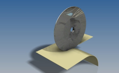
The cutting principle is based on creating a scissor movement with two sharp rollers running directly alongside each other.
The cutting section has a set of drawing rolls that
draws the material off the feed roll and feeds it in at
a constant rate whilst the length of the material is measured by encoders on the drawing rolls.
Cross cutting
A cross cut is always the full width of the material. A rolling blade cuts along a counter blade equivalent to a pair of scissors to ensure it can cut the toughest materials. The blades can be removed for sharpening when necessary.

Slit cutting
Three slit cutting blades are fitted as roller blades cutting against a lower blade simulating a scissor movement. The standard machine is designed to allow either cross cutting or lengthwise cutting.

Due to the stiffness of the material a rolling guide system is set up in order to guide the outfeed into a roll shape. After the cross cut the roll is stabilised with a strap and ready to move to an output trolley. The roller shaft is fitted with suction cups to draw the material onto the shaft..
When the roll is ready to be removed the rollers on the shaft enable the stabilised roll to be pulled onto a transport trolley.
Optionally the rolling system may be bypassed and shorter sheets led onto the output table.

Specifications
10 m/min; minimum thickness depending on the stiffness of the material, maximum thickness 3 mm glass fibre reinforced in straight x and y movements. Tests would be required with your material range to establish the cutting parameters.
Left over material is vacuumed away directly after cutting.
Optional freeform cutting, allowing the cutting units to turn and move in accordance with a CAD/CAM cutting file. The turning circle and thus the cutting radius is limited by material stiffness and cutting resistance.
Optional: Output trolley for output roll.
Optional: Handling equipment for assisted or automatic loading and unloading of material rolls at both ends of the machine.
Principle of operation

The system uses one edge of the material as a guide to the positioning of the slits. This means that there is a minimum stiffness of the material required. The same goes for the lengthwise determination of material length, which is done with a counter on the drive rolls, which by nature requires a stiff cloth or material. .
Current proven performance limits:
Max roll width : 3.2 m
Roll diameter : up to 0.8 m
Material thickness : ca 1.5 to 3.0 mm plate or stiff reinforced cloth. Max variation: 0.5 mm.
Proven material types : Pecolit 1.0 to 3.0 mm thickness. Alumium sheet around 1.0 mm thickness
Cutting speed : up to 10 m/min
Control units : Siemens 7 based PLC with a 7-inch touch screen according to Wadcon standard. All movement can be manually overridden if necessary. Each movement and adjustment has its own alarm and control circuit. Alarms are reset centrally, not individually.
English language control panel for three lengthwise and one traverse cuts..


